
Piping
Plot plan and equipment spacing — the drawing everything else inherits
What actually sets the distance between equipment, the four drivers that pull against each other, the pipe rack as the spine and how its tiers are allocated, prevailing wind and fired equipment, roads and containment, and why a plot plan mistake cannot be recovered downstream.
Standards referencedOISD-STD-118API 752API 753ASME B31.3NFPA 59A
The plot plan is the drawing that everything else inherits. Foundations, racks, roads, cable routes, drainage and every line in the unit follow from it, and it is frozen early — long before most of the detail that depends on it exists.
That asymmetry is the whole reason it deserves attention from a piping engineer. A route can be redrawn for the price of a revision. A column in the wrong place is a poured foundation, and the consequence shows up as a problem somewhere else entirely — usually as an NPSH margin that cannot be found.
The four drivers, pulling against each other
Process. Short transfer lines, gravity flow where it is wanted, columns close to their pumps so suction lines are short, reboilers and condensers near what they serve, and expensive alloy runs kept short. This is where piping has the strongest claim, because the consequences are quantifiable.
Safety and fire separation. Minimum distances between hazard sources and between hazards and people. OISD-STD-118 carries the Indian layout requirements; API 752 and API 753 govern where permanent and portable buildings may be placed relative to the process. Fired equipment is separated and placed upwind of hydrocarbon sources, so a release is carried away from the flame rather than towards it.
Maintenance. Crane standing, bundle pull, rotor withdrawal, laydown, and roads that a vehicle can actually use. Deferred to repeatedly, and the deferral is what produces a unit that is expensive to maintain for thirty years.
Construction. Erection access, lifting over rather than through, and where modules can be set down. Temporary, but if it is impossible the schedule pays.
These pull in different directions. Process wants everything close; safety wants it apart; maintenance wants room between. Resolving them is what the plot plan is.
The rack is the spine
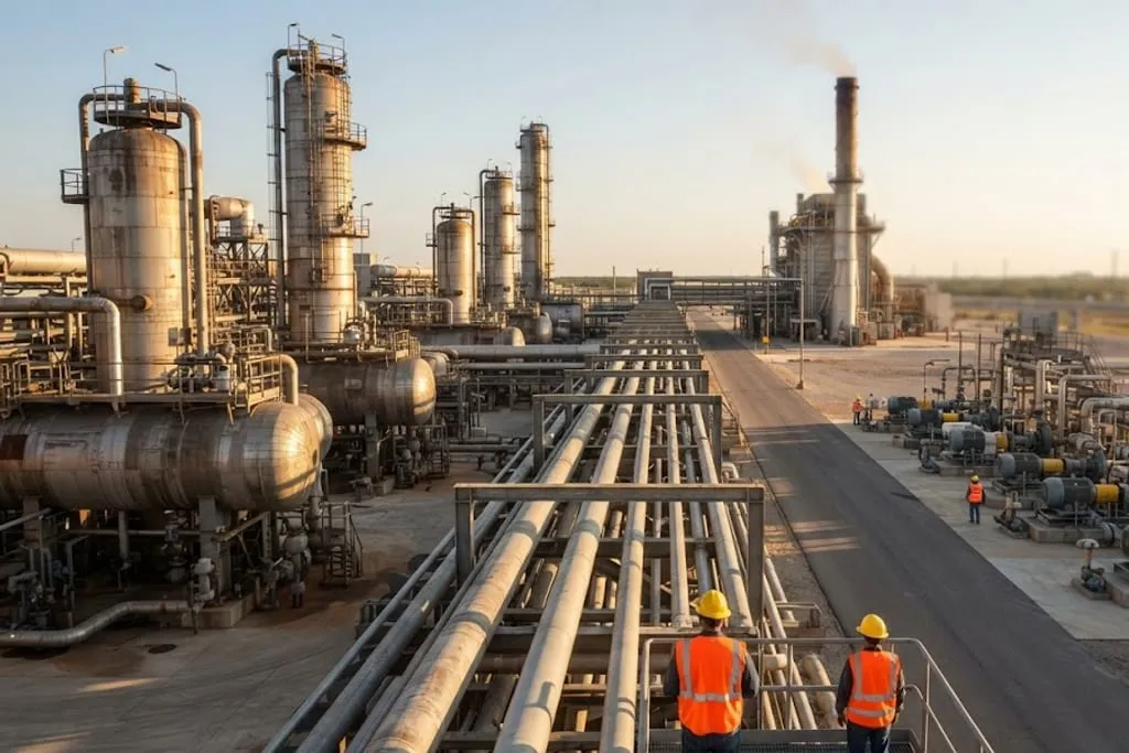
Almost every process unit is organised around a pipe rack with equipment either side of it. Get the rack right and the unit lays itself out.
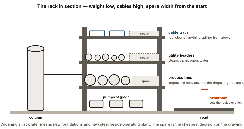
Tiers. Process lines low — they are the biggest, the heaviest, and they connect to equipment at grade on both sides, so short drops matter. Utilities above them. Electrical and instrument cable trays commonly on the top tier, clear of anything that could spill onto them from above.
Width and spare capacity. A rack is widened once, at the start, on paper. Widening it later means new foundations and new steel beside operating plant. Carrying something like twenty per cent spare from the outset is among the cheapest decisions available.
Bent spacing sets the span for every line on the rack, and therefore the support spacing, and therefore whether small bore needs intermediate steel.
Expansion. The rack grows too, and it carries the shoes and guides with it. See anchors, guides and restraint schemes.
Pumps under or beside the rack is the standard arrangement — the lines are already overhead and the drops are short. The price is maintenance access, which has to be preserved deliberately.
Wind, ignition and people
Three placement decisions that are made once and cannot be unmade:
- Fired equipment upwind of the hydrocarbon inventory, and separated from it.
- Occupied buildings — control rooms, substations, workshops — sited against a blast and exposure assessment, not against convenience.
- Escape routes and muster points, which need two ways out of anywhere people work and a route that does not pass the thing they are escaping from.
Roads, access and containment
Roads carry fire water appliances, cranes and heavy lifts. They need width, turning radius, and headroom where pipe crosses them — and that headroom is a piping constraint which has to be known before a rack elevation is fixed.
Containment is a layout outcome. Paving, kerbs, the fall across an area, where the catch basins are and what they drain to — all set here. A spill follows the ground, not the drawing.
How it is actually produced
Block plan, then plot plan, then equipment layout, then the piping study, then the three-dimensional model — with model reviews at roughly thirty, sixty and ninety per cent.
Those reviews exist for one reason: the people who will operate and maintain the plant are the only ones who reliably find the valve nobody can reach, the bundle that cannot be pulled and the platform with one way off it. Everything they find at thirty per cent is a drawing revision. The same finding after handover is a permanent operating restriction. See access, operability and maintenance space.
What piping must push back on
Two things, specifically, because they cannot be recovered later:
- Distance from a source vessel to its pump. Friction loss is NPSH available, and no amount of later skill replaces margin given away here. See pump piping layout.
- Rack width and headroom. The flexibility that hot lines need is space, and if the rack has none, the loops do not fit. See expansion loops and offsets.
Both arguments have to be made while the plot plan is still soft, with numbers. Afterwards they become somebody’s permanent problem.
What to take away
- The plot plan is inherited by everything and frozen early.
- Four drivers — process, safety, maintenance, construction — and they conflict by design.
- The rack is the spine: process low, utilities above, cable trays high, and spare capacity costs almost nothing now.
- Fired equipment upwind and separated; occupied buildings sited by assessment.
- Roads and headroom constrain rack elevation; paving and falls decide where a spill goes.
- Brownfield starts with what is already buried and already built.
- Model reviews are where operations and maintenance find what designers cannot.
- Piping must argue early for pump proximity and rack width, with numbers.
Check your understanding
10 questions. Nothing is recorded — this is just for you.