
Piping
Anchors, guides and restraint schemes — deciding where the pipe may move
A restraint scheme is one decision for a whole run, not a scatter of supports. Where an anchor belongs, what it actually carries once friction is counted, line stops against full anchors, the gap that is the design, and the accidental anchors that site creates.
Standards referencedASME B31.3ASME B31.1MSS SP-58MSS SP-69API 610
A support placed on its own answers one question: what holds the pipe up here. A restraint scheme answers a different and prior one: where is this line allowed to move, and where is it not?
Get the scheme right and the individual supports fall out of it. Get it wrong — place supports one at a time as each span runs out — and you produce a line that is held everywhere and flexible nowhere, which is exactly the condition thermal expansion punishes.
The scheme, in the order it is actually decided
- Find the points where movement must be near zero. Equipment nozzles, spec breaks into a sensitive system, tie-ins to existing plant that is not going to move for you.
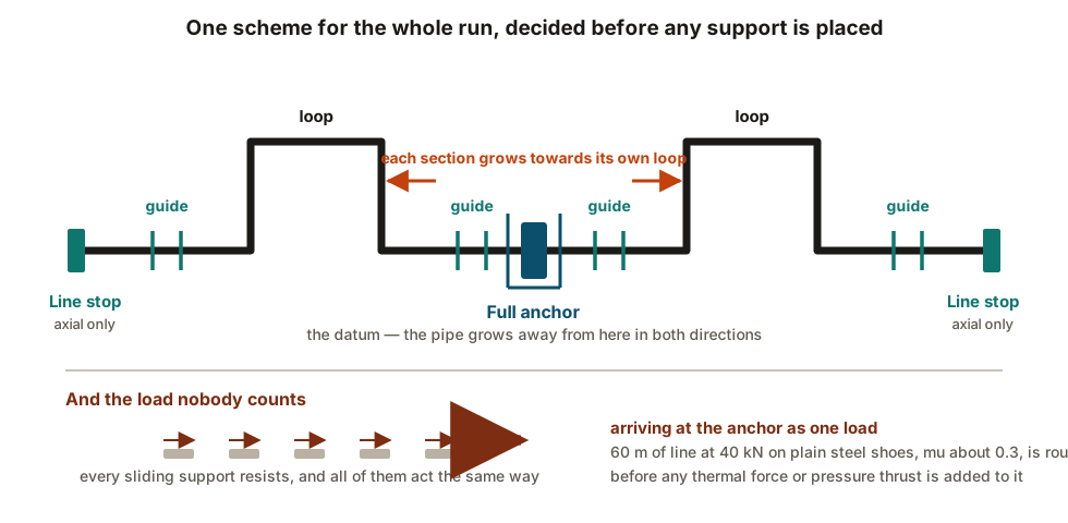
- Place the anchors. Each anchor declares a datum: from here, the pipe grows away in both directions.
- Give each section somewhere to grow. A loop, an offset, a change of direction long enough to flex. See expansion loops and offsets.
- Guide each section so the growth is driven into that flexibility rather than wandering sideways.
- Then support the weight, with the spans and types that follow.
Steps one to four are the design. Step five is the part that gets drawn first by anyone who has not been taught this, and it is the part that matters least.
What an anchor actually carries
More than the thermal force, and the extra is routinely missed.
The thermal force from each side, which partly cancels when the two sections are similar and emphatically does not when they are not.
Friction from every sliding support in the section. This is the one people forget. Each shoe resists sliding, every one of those resistances acts in the same direction, and they all sum at the anchor.
Line weight, 60 m supported          ≈ 40 kN
Plain steel-on-steel shoes, µ ≈ 0.3
Friction arriving at the anchor      ≈ 0.3 × 40 = 12 kN
Twelve kilonewtons, present every time the line moves, from nothing more exotic than pipe resting on beams. Low-friction slide plates take µ down towards 0.1, and that — rather than any virtue of their own — is why they appear on long hot runs.
Pressure thrust, if there is a bellows anywhere in the section. See expansion joints and bellows, and note that this one is present whenever the line is pressurised, hot or cold.
Full anchors, line stops and the difference
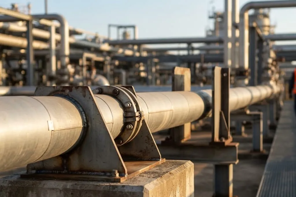
A full anchor fixes all six degrees of freedom. It is expensive in structure and it attracts every load in the section.
A line stop, or directional anchor, arrests movement along the pipe axis only and leaves the line free vertically and laterally. Very often that is all the scheme actually needs — you wanted to define where the section grows from, not to prevent all motion — and it costs a fraction of the structure.
Reaching for a full anchor when a line stop would do is one of the quiet ways a piping design gets expensive, and it also makes the stress result worse rather than better, because every restraint you add is another place the line can be overloaded.
Guides, and the gap that is the design
A guide holds the line sideways and lets it grow lengthways. Its job in the scheme is twofold: keep the growth pointed at the flexibility, and stop a compressed run from buckling out of line.
The gap between pipe and guide is sized so the line never binds through its full travel, in both directions, with the pipe at any temperature it will see. It is a dimension on a drawing for a reason.
Friction and the neutral point
On a very long run, friction accumulates. Each shoe adds its resistance, and at some distance along the line the accumulated friction equals the force available to move the pipe. Beyond that, the line does not move at all.
That location is the neutral point, and it behaves like an anchor nobody drew. On long transfer lines and rack runs it has to be understood rather than discovered, because it determines where the movement actually ends up — which is not necessarily where the drawing assumed.
Protecting equipment with the scheme
The most useful thing an anchor does is often not to control the pipe but to protect something else. An anchor placed between a hot run and a pump means the growth of that run terminates at the anchor instead of arriving at the nozzle.
This is why a loop without an anchor frequently fails to help. The loop only absorbs what is driven into it; without a restraint defining the end of the section, the growth takes the softest path available, and a machine nozzle is very often exactly that. See nozzle loads and allowables for what that costs.
The cases the scheme has to survive
Not just the hot case. Hydrotest governs more often than people expect — a vapour line full of water can weigh several times its operating weight, and the springs, supports and steel all have to take it. Steam-out, regeneration and winter minimum each produce their own movement, in their own direction.
A scheme is only correct if it is correct in all of them.
What to take away
- The scheme is one decision for a whole run, taken before any support is placed.
- Anchors first, flexibility second, guides third, weight supports last.
- An anchor carries thermal force plus accumulated friction plus any pressure thrust — friction alone can be tens of kilonewtons.
- A line stop is usually enough, and far cheaper than a full anchor.
- The guide gap is a dimension, not untidiness.
- Accidental anchors are made in the field — grout, packed insulation, tightened clamps — and are invisible afterwards.
- On long runs, friction creates a neutral point that acts as an anchor nobody drew.
- A loop only absorbs what the restraint scheme sends it.
- The scheme must work in the hydrotest and cold cases, not only the hot one.
Check your understanding
10 questions. Nothing is recorded — this is just for you.