Piping
Nozzle loads and allowables — the constraint that really governs hot piping
Why machine nozzle allowables are so small, where they come from for pumps, compressors, turbines and vessels, what exceeding them actually does, why the symptom surfaces in somebody else's report, and the design and field rules that prevent it.
Standards referencedAPI 610API 617NEMA SM-23API 686API 660WRC 537ASME B31.3
Ask a piping engineer what limits a hot line and the answer is usually the pipe. It very rarely is. The binding constraint on most hot piping is the equipment nozzle at the end of it, and the number is far smaller than people expect.
Why the allowables are so small
A pump casing is not a pressure vessel with a flange on it. It is a precision housing holding a shaft, wear rings, bearings and a mechanical seal in a geometric relationship measured in fractions of a millimetre.
Pull on it with a pipe and the casing distorts. Not visibly, and not anywhere near its structural limit — but enough to move the shaft relative to its bearings and its seal faces. That is the whole basis of the limit, and it is why a casing rated for 50 bar internal pressure has nozzle allowables that a few metres of unsupported hot pipe will exceed.
Where the allowables come from
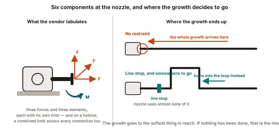
Pumps — API 610. Forces and moments tabulated by nozzle size and direction, for suction and discharge. The standard also sets out the conditions under which higher loads may be acceptable, provided wider displacement criteria on the whole machine and baseplate are satisfied. Those tables are what a piping stress report gets compared against.
Compressors — API 617. Allowables commonly expressed relative to the turbine basis, and like pumps, small.
Steam turbines — NEMA SM-23. The tightest of the three, and structurally different: as well as a limit on each connection, there is a combined limit on the resultant of all of them resolved to a common reference. Passing every nozzle individually does not pass the machine. On a turbine-driven train, the turbine almost always governs.
Exchangers and air coolers. API 660 and API 661 equipment carries its own nozzle limits, and air coolers in particular are flexible structures that move.
Vessels and columns. No universal table. The allowable comes from a local stress check on the shell at the attachment — WRC 537 and its predecessors — and the vessel designer sets it. The other half of a column nozzle is that it moves: a tall hot column grows, and its nozzles travel with it, so the piping has to follow rather than resist.
What exceeding them actually does
Rarely a rupture. Almost always a slow, expensive misdiagnosis:
- Casing distortion moves the shaft relative to its bearings and seal.
- Coupling and alignment go out, and stay out — a cold alignment done with the piping disconnected is meaningless if the piping pulls the machine when it is bolted up.
- Mechanical seals fail repeatedly, and get replaced repeatedly.
- Bearing temperatures and vibration drift up.
- On vessels, local shell stress and in time cracking at the nozzle.
Finding it in the field
Two tests, both cheap, both conclusive:
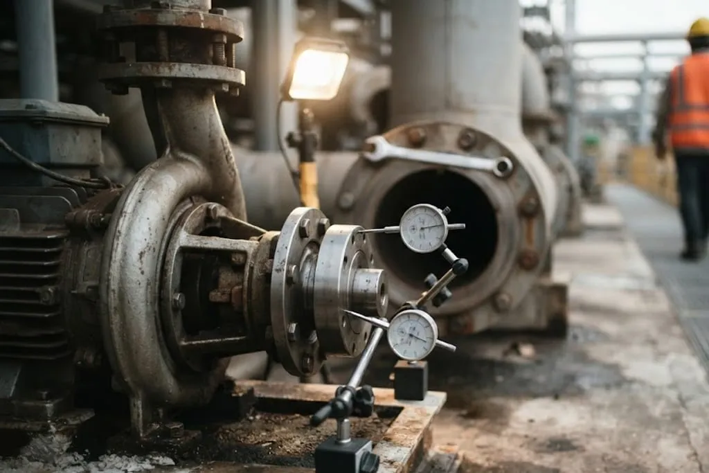
Break the flange. Slacken the bolts at the machine connection. If the joint springs apart, or the faces move, the pipe was being forced into place and the casing was carrying that force.
Watch the shaft. Put dial indicators on the shaft and have someone break the flange. Movement at the shaft when the piping is released is pipe strain, measured directly.
API 686 sets criteria for flange gap and parallelism when piping is connected to machinery, which is the standard to point at when the answer is “it went together fine”.
Designing it out
In rough order of effectiveness:
- Put a restraint between the hot run and the machine. The growth stops at the anchor or line stop instead of arriving at the nozzle. See anchors, guides and restraint schemes.
- Give the short connection some flexibility. A straight stiff run from a rack to a nozzle has none. A change of direction with a usable leg costs almost nothing at design stage.
- Carry the weight. The first support off the machine takes the dead load so the nozzle does not — while not itself becoming an accidental anchor.
- Use the right spring. Near equipment the load variation limit tightens to around 10 per cent, and where that cannot be met, a constant effort unit. See spring hanger selection.
- Support heavy valves and actuators independently. Dead weight is the easiest load of all to deliver into a nozzle.
- Never spring the flange to fit. A mismatch pulled together with bolts or a crane is a permanent load on the casing.
The cross-check nobody owns
The analyst produces nozzle loads. The vendor produces allowables. Somebody has to put the two side by side.
On a surprising number of projects that comparison belongs to no named person, because it sits exactly on the boundary between piping, rotating equipment and the package vendor. It is worth assigning explicitly, because the alternative owner of that check is the machine.
What to take away
- The governing constraint on hot piping is usually the nozzle, not the pipe.
- The limit exists to keep the casing undistorted, not to stop it breaking.
- API 610 for pumps, API 617 for compressors, NEMA SM-23 for turbines — and the turbine usually governs, with a combined limit as well as individual ones.
- Vessel nozzles have no table; the allowable comes from a local shell stress check, and the nozzle moves as the vessel grows.
- Overload shows up as seal, alignment and vibration trouble in somebody else’s report.
- Break the flange and watch it — the cheapest diagnosis on the plant.
- Prevent it with a restraint before the machine, real flexibility in the connection, weight carried properly, and tight springs.
- Name an owner for the loads-against-allowables comparison.
Check your understanding
10 questions. Nothing is recorded — this is just for you.