
Piping
Corrosion loops and piping circuits — the two groupings an RBI study is built on
Why a corrosion loop and a piping circuit are different things, how each one is drawn and bounded, what goes wrong when a circuit is too big or a loop mixes two streams, and why every number downstream depends on getting these right.
Before an RBI study calculates anything, it divides the plant up twice — once by why things corrode, and once by where they will be measured. These are the corrosion loop and the piping circuit, and they are not the same thing.
Almost every problem in a badly executed study traces back to one of these two groupings being drawn carelessly.
The corrosion loop: why
A corrosion loop groups everything exposed to the same fluid, in the same materials, at the same conditions — and therefore subject to the same list of damage mechanisms.
It is a process idea, so it is drawn on the PFD. A loop might be the reactor feed circuit, or the column overhead system, or the caustic circulation.
A documented loop carries: loop number and name, a process description, its start and end points, the major equipment inside it, the potential damage mechanisms, and the critical process parameters that would change them.
Note what is not on that list. No thickness readings, no corrosion rates, no dates. The loop is the reasoning.
The piping circuit: where
A piping circuit is a length of piping inside one corrosion loop, small enough that a single inspection plan and a manageable set of measurement points can sensibly represent all of it.
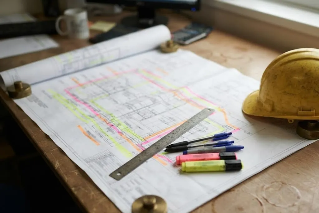
It is an inspection idea, so it is drawn on the P&ID and carried down to the isometrics.
| Question it answers | Why would this corrode, and by what mechanism? | Where do I measure, and how often? |
|---|---|---|
| Grouped by | Process fluid, material of construction, operating temperature and pressure, and the resulting damage mechanisms | A length of piping inside one loop that can reasonably share a single inspection plan |
| Drawn on | PFD mark-up — the process view | P&ID mark-up and isometrics — the line-by-line view |
| Typical size | A process section: reactor feed, column overhead, caustic circulation | A handful of lines of the same spec with the same exposure |
| Owned by | The corrosion or materials engineer | The inspection engineer |
| Carries | Damage mechanisms, critical process parameters, materials, integrity operating windows | CMLs, thickness readings, corrosion rates, remaining life, inspection dates |
| Bounded by | A change in fluid, material, phase or temperature that changes the mechanism | Spec breaks, isolation valves, equipment nozzles, or a change of line class |
| Gets it wrong by | Grouping two streams that corrode differently, so the mechanism list fits neither | Being so large that one reading is asked to represent lines that do not behave alike |
No rows match that filter.
The two are routinely used as though they mean the same thing. They do not: a corrosion loop answers why something corrodes, a piping circuit answers where you put the measurement. One loop normally contains many circuits.
One corrosion loop normally contains many circuits. The loop says this system suffers under-deposit corrosion at the cold end; the circuits say and these are the eleven places we will measure it.
Where a circuit stops
A circuit ends where something that governs its behaviour changes:
- a spec break — different material or rating
- an isolation valve that defines an operable section
- an equipment nozzle, because the exposure changes on the other side
- a change of line class, because the design basis is no longer the same
Diameter alone is not a boundary. A 6 in. line reducing to 4 in. in the same service, same material, same conditions is still one circuit.
How the grouping is actually built
The sequence is deliberate, and each step is a meeting rather than a calculation.
Loops first, from the PFDs, with the process, operations and inspection engineers in the room together. The corrosion engineer proposes the boundaries; the people who run the plant say where the conditions are not what the drawing claims.
Circuits second, from the P&IDs, once the loops are agreed. This is where special components are picked out individually — dead legs, injection points, mixing points, soil-to-air interfaces, small-bore connections — because they do not behave like the pipe around them and cannot be represented by it.
CMLs last, placed on the isometrics and then verified physically. A point chosen on a drawing and found on site to be behind cladding, under a support or six metres up with no access is not a monitoring location.
Why this is the foundation
Everything downstream inherits these boundaries.
The damage mechanisms come from the loop. The CMLs are placed to catch those mechanisms. The corrosion rates come from readings at those CMLs. The remaining life comes from the rates, the interval from the remaining life, and the inspection plan from the interval.
What to take away
- A corrosion loop answers why, a piping circuit answers where. They are different groupings for different purposes.
- Loops are drawn on the PFD by process grouping; circuits on the P&ID by inspectable section.
- A loop is correct when one list of damage mechanisms is honestly true of everything in it. Different metallurgy means a different loop.
- Circuits are bounded by spec breaks, isolation valves, nozzles and line class changes — not by diameter.
- Too-large circuits hide thinning by averaging it away. Too-small circuits collapse under administration.
- Special components are separated out, because they do not behave like the pipe around them.
- Get the grouping wrong and everything downstream is precise and wrong, with nothing to signal it.
Check your understanding
7 questions. Nothing is recorded — this is just for you.